
In automotive plastics, dimensional precision is directly tied to functionality, aesthetics, and assembly efficiency. With complex geometries, Class-A surfaces, and tight GD&T tolerances, we cannot rely on visual inspection or CMM audits alone. Checking fixtures provide a robust, repeatable solution for validating parts against design intent — directly on the shop floor.
The Role of GD&T in Fixture-Based Validation
Checking fixtures are designed to replicate datum structures and functional conditions defined in the drawing. By integrating GD&T principles, fixtures ensure critical features meet OEM requirements such as:
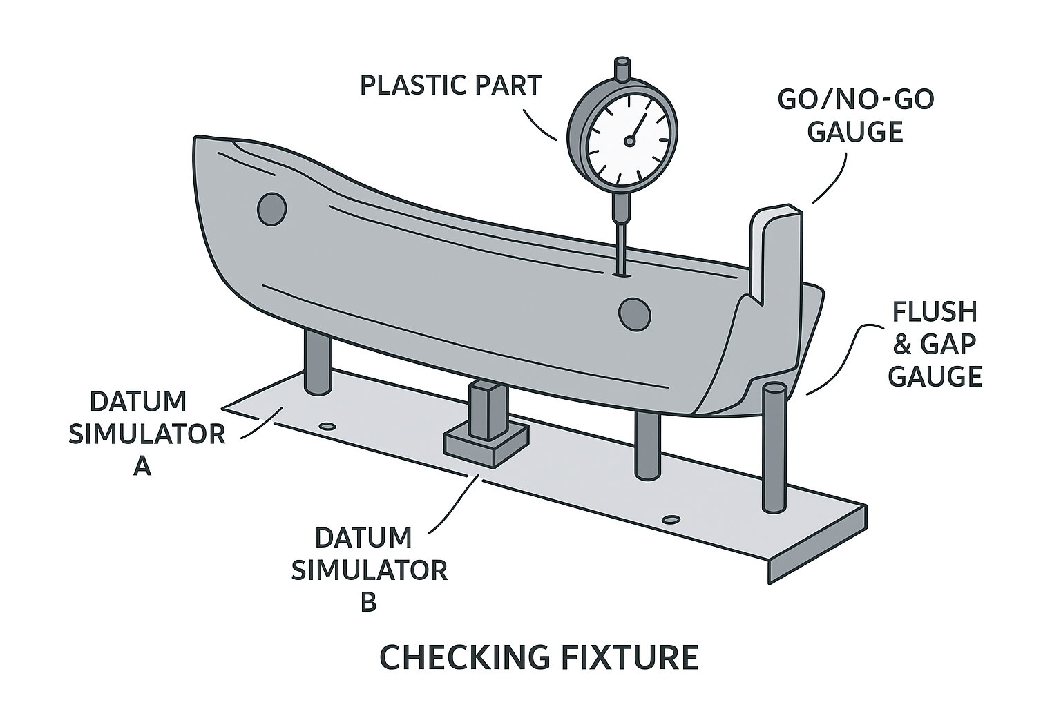
- Datums (A, B, C): Fixtures use precision datum simulators (pins, pads, and slots) to locate and secure the part according to its RPS (Reference Point System).
- True Position: Go/No-Go gauges confirm hole and slot positions relative to the datum structure, ensuring assembly fasteners or clips engage correctly.
- Profile of a Surface: Dedicated check points (often with dial indicators or digital probes) validate the contour accuracy of Class-A surfaces and visible trims.
- Flatness/Parallelism: Base pads and feeler gauges confirm mounting faces remain within microns of tolerance — critical for tight assemblies like instrument panels.
By combining these checks, fixtures act as a physical representation of the CAD model and the drawing’s GD&T requirements.
Core Elements of a Checking Fixture
A well-engineered automotive fixture typically includes:
- Datum Locators: Hard-mounted pins, rests, or V-blocks that replicate the part’s datum reference frame.
- Go/No-Go Gauges: Plug, ring, or contour gauges to quickly validate feature size and location.
- Flush & Gap Gauges: Adjustable feeler or stepped gauges to confirm alignment of mating Class-A surfaces.
- Slide Units & Clamps: To simulate assembly constraints or hold flexible parts in the correct condition during inspection.
- Digital Sensors: Increasingly, fixtures incorporate LVDTs or touch probes to capture data for SPC directly from the line.
- Ergonomics: Fixtures are designed to be lightweight, robust, and operator-friendly, enabling repeatable results with minimal training.
Example in Practice
Take an exterior bumper fascia — one of the most dimensionally demanding moulded parts in a vehicle:
- Datum Setup: The fixture establishes the bumper’s primary, secondary, and tertiary datums using dedicated pads and pins.
- Hole/Slot Validation: Go/No-Go pin gauges check mounting points for true position relative to datums.
- Flush & Gap: Integrated feeler gauges replicate how the fascia will interface with headlamps and fenders, ensuring consistent styling lines.
- Profile Checks: Contact points with dial indicators measure critical surfaces to confirm Class-A aesthetics.
This system ensures that before the fascia leaves the moulding shop, it is functionally and visually compliant with OEM standards.
Why This Matters for Automotive Injection Moulding
- Prevents costly rework at final assembly.
- Ensures PPAP readiness with traceable, repeatable data.
- Provides real-time process feedback for tool wear, shrinkage, and material variation.
- Bridges the gap between CAD intent and physical reality.
In short: Checking fixtures are not passive gauges — they are engineered systems built on GD&T principles, tailored to simulate real assembly conditions, and critical to ensuring that injection-moulded plastic parts meet the automotive industry’s uncompromising standards.